The engineer has always been in control at Daimler-Benz. The German for ‘stylist’ is no doubt a very long word, but his influence is relatively short. Market forces are not ignored, but a new body on a Mercedes-Benz is normally only introduced as outer covering for a new advanced design of car. The engineering comes first, the styling second.
The engineering comes first, the styling second. Having abandoned their long battle with the swing axle rear suspension, Daimler-Benz adopted the semi-trailing arm rear suspension and refined it. In conjunction with a well-developed double-wishbone system at the front, using unequal-length wishbones suitably angled to give anti-dive geometry, the mid-1970s range of Mercedes-Benz cars seemed to represent the ultimate in conventional suspensions. When tested by Motor in 1974 the 450 SEL was pronounced as ‘simply magnificent’.
There are improvements on the Citroen system. For example, suspension height can change when the engine is not running. This is because the central reservoir is charged to a higher pressure than that required for normal operation. This high-pressure reservoir is particularly valuable when changing a flat tyre.
The pressure line to any particular suspension unit can be isolated during a wheel change then repressurized from the reservoir afterwards. If the pressure supply fails by pump failure or other cause, both axle circuits can be isolated to complete the journey. Another improvement is the basic suspension geometry which, unlike that on the Citroen, is designed to maintain near-verticality of the outer wheels when cornering.
Large-bore connecting pipe between the hydraulic suspension cylinder and the gas ‘sphere’. This gives the designer more freedom in the disposition of the components. The gas reservoir (the sphere) can be fitted neatly into the side of the rear wheel arch. The Citroen engineers solve the difficult problem of intrusion into the passenger space by placing the cylinder/sphere unit in a near-horizontal position.
Angular movement of the center point of the anti-roll bar is used to actuate the level controller. The detail design of the suspension cylinder. The damper valves are carried in the piston, not in the base of the gas reservoir as in the Citroen. Any leakage past the piston rod seals is returned to the main reservoir via the special return lines.
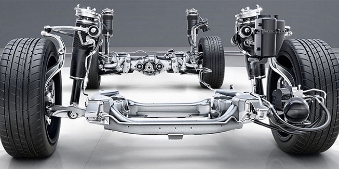
The hydraulic supply reservoir is the large cylindrical vessel situated in front of the front suspension cylinder on the right. The gas vessel associated with this reservoir can be seen adjacent to the suspension ‘sphere’ on the right of the drawing. Anti-dive and anti-squat had already been built into the 450 SEL suspension before the adoption of hydro pneumatic suspension.
Last word
Anti-roll provision, however, had to be supplemented. With gas suspension bump and rebound rates very much lower than those used with coil suspension, it was necessary to provide much stiffer anti-roll bars to achieve the same roll resistance.